Summary
I’m still behind schedule but am making progress! I’m finishing up details on the MCM, and over the weekend will do design work on the rest of the machine and the parts I’ll need for characterization (cap probe holders, for example). I’ll be able to start machining next week.
Analysis worksheets for this week:
- Blade flexure out-of-plane stiffness correction factor worksheet
- Latest error budget
- Geared stepper motor and leadscrew resolution
- X stage flexure design worksheet
Error budget updating and sanity-checking
Last week I was deciding on whether I should go with flexural bearings, rolling contact, or a kinematic sliding contact stage for my most critical module (the knife positioner – has to position to an accuracy of 100nm or better). The lowest risk solution is a flexure stage, since I know for sure that these can achieve repeatabilities on that scale. I would have to work harder to make the other two types of bearings perform at that level (I would be higher up on the cost/performance curve).
With flexural bearings, I need to be careful that my stiffnesses are appropriate to my application (this is true for any bearings, but with flexures it’s easy to accidentally decrease a stiffness that you wanted to keep stiff!). I need to use the error budget as my guide – in PUPS 7 I noticed that I needed to update the compliance matrices for my two flexural bearing stages (and in general I had been sloppy with double-checking to make sure there were no errors). I created analytical models for blade flexures (I used Dr. Layton Hale’s thesis to get some of the more complicated analytical solutions, but it turns out using simple beam equations is almost good enough). Once I knew my target stiffnesses I could do the detailed flexure designing (what range? stresses? fatigue? that sort of thing).
I went into the error budget and updated the compliance matrices for my flexures, and because of how important this is to my machine I decided I would validate my analytical flexure stiffness models with FEA. What I found was that my analytical model overpredicted the out-of-plane stiffness of a single blade flexure by a factor of two (I treated it as a fixed-guided beam), and this overprediction propagated into the rotational stiffnesses, so I needed to figure out why this is happening (the other stiffnesses were within a few percent).
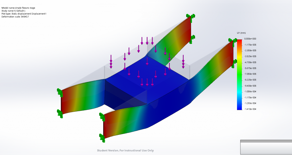
I talked to Marty about this and he mentioned that for deep beams, one needs to apply a correction factor for internal shear. I looked in the literature to find solutions to deep beams (I didn’t want to solve the differential equations from scratch). I rearranged the formulae and found that you could write the internal shear correction factor as a dimensionless factor that relies on the depth-to-length ratio. I applied this correction in my error budget and the analytical model was within a few percent of the FEA (I tried it with various beam depths, and the corrected stiffness was consistently within at least 10%).
Design work
My MCM is the knife positioner module with a flexure bearing and I’ve been focusing on narrowing down what it will look like.
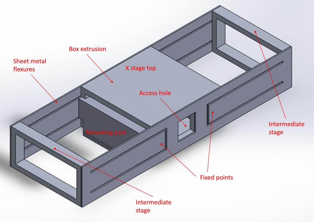
To get the range I needed, I could either have very long flexures or I could fold them over – I chose to have the more compact, but more complex, design. The flexures themselves are cut into sheet metal in two pieces; if I minimize the possibility of misaligning flexures during bolting-together, I’ll minimize parasitic error motions caused by those misalignments. These will also cut very quickly on the waterjet and so will be very cheap to make. I’m working on finalizing the details and streamlining the design as much as I can.
Differential leadscrew concept
I figured I could get high range and high resolution by using a differential leadscrew arrangement, but as I worked on this I realized that the complexity was increasing
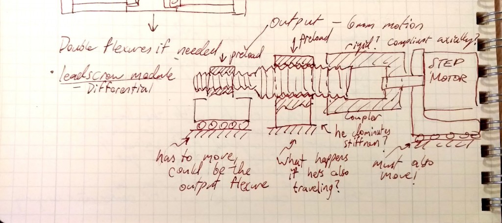
The key issues I faced with this design were:
- The motor has to move with the screw, which means I need another bearing!
- I calculated that the screw has to move approximately 2 inches to get a full 1/4″ of motion at the output
I wondered if I could get away with a simpler solution, with a geared-down motor directly driving a fine-pitch screw.
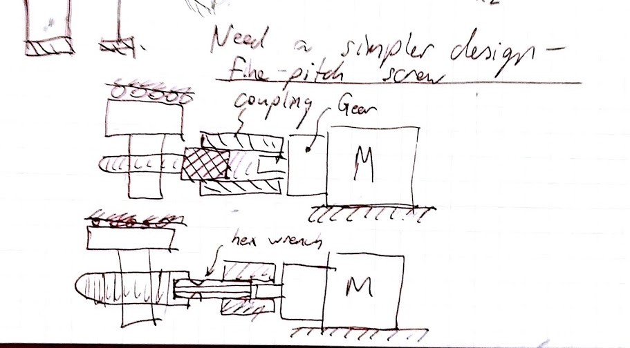
This is a much simpler, more compact design, but will it work effectively? The motor and gearbox are rated for 50 N of load, so it will handle the axial load comfortably (I push/pull with a maximum of 15N). What about misalignments? I won’t be able to get this thing perfectly aligned, I may have to build in some decoupling flexures into the carriage nut (or use a non-rigid coupling). I will figure out which misalignments are most likely to be problematic and decouple those. The nuclear option: I have a design for a decoupling stage that can move in every degree of freedom except the wind-up direction. I could attach the leadscrew nut to this stage, and then couple this stage to the X stage via a wire flexure to transmit only the axial component of motion.
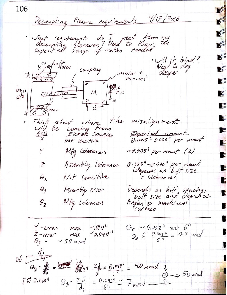
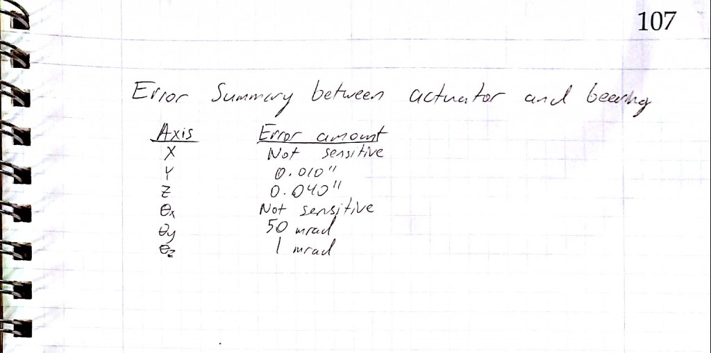
This is getting complicated! I’m not comfortable with this concept because I would have to design it to move as far as my X-stage – I would have to double-design my X stage! First I need to asses which error motions are important , and roughly what I expect their magnitudes to be given my assembly and machining tolerances (which errors would cause the system to bind up or generate huge loads?). Could I use an off-the-shelf coupling? Below is a screenshot from my notebook where I estimated what these errors would be.
A quick survey of couplings on Mc-Master shows that the helical-type couplings only tolerate parallel misalignments of a few thousandths and angular misalignments of a few degrees. Most of my parallel errors are creeping in due to using bolts as clamping+alignment. If I use dowels to locate parts (so that my positioning uncertainty is reduced from around 0.020″ to about 0.002″), I can reduce the parallel errors by about an order of magnitude. I can now use a helical coupling.
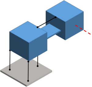
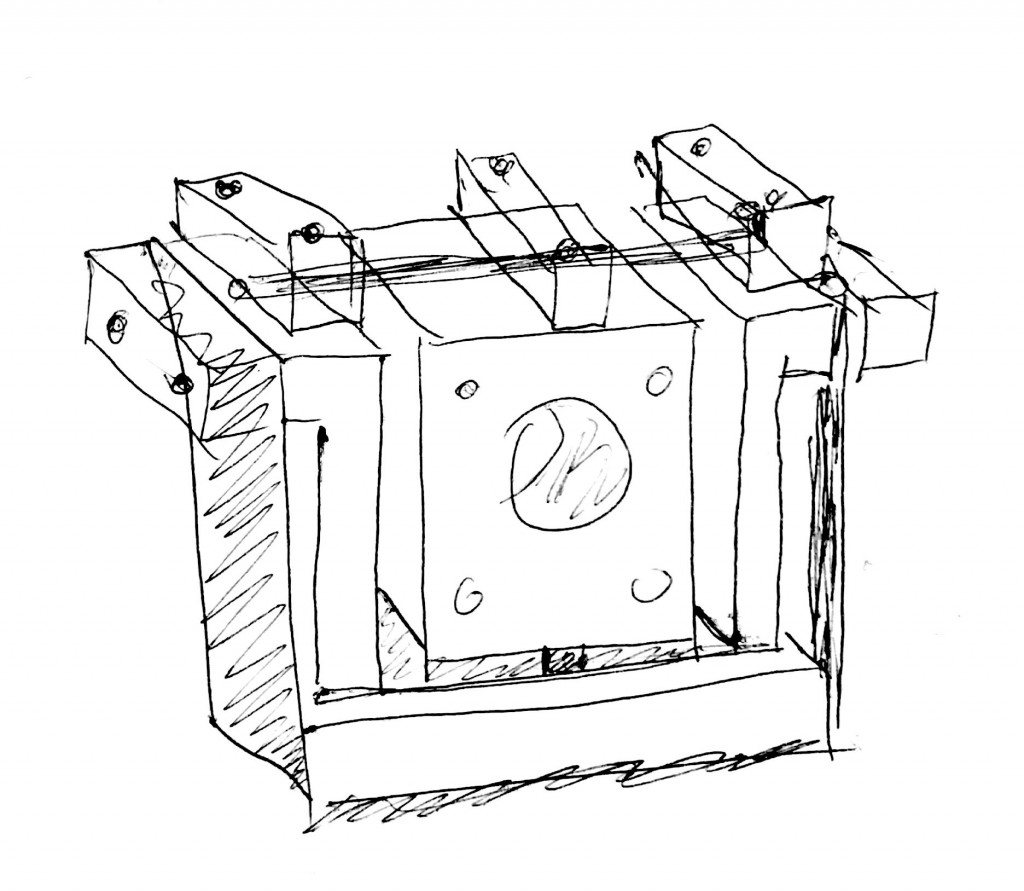
Alternatively, here’s a modified error motion absorbing concept with 4 degrees of freedom (this is schematically the same as the “dancing man” flexure from 2.72, which is used to decouple leadscrew error motions from the carriage while remaining stiff in the torsional and axial directions). I don’t have lots of room inside my carriage so I’d prefer to build this into the motor mount.
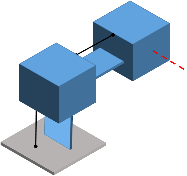
An implementation of the above schematic is shown below. It’s more complex than the helical coupling, but I’ll keep this in my quiver in case the helical coupling doesn’t work out.
For my actuator I’ve chosen a stepper motor with a gear reduction of 14:1 – this combined with a fine-pitch screw (1/4-80) will theoretically give me a resolution of ~ 60 nm. Steppers are inexpensive and simple to interface with, and driver chips are cheap and ubiquitous nowadays thanks to the DIY 3D printer crowd. Torque to actuate shouldn’t be a problem – I calculated a torque-to-move of about 0.01 N-m (from the Geared Stepper motor worksheet) under a heavy load of 50 N; my motor will be able to exert around 1 N-m. The gearbox is rated for a 50N axial load and a 100N radial load, and my current flexure design will take at most 20N to move.
For now – I need to finish detailing the MCM and finish working on the rest of the machine. My next step is to detail the MCM (bolts, etc), cut out the parts, and then test it