- Make /acquire the parts for your machine and measure and compare to the drawings. Did you achieve the desired tolerances?
- Assemble the modules and then the machine, and comment on did it go together the way you expected?
- Measure performance and compare to that predicted.
- Accuracy
- Repeatability
- Resolution
- Stiffness
- Update your predictive model accordingly
- Celebrate!
Author: elpresidante
Seek and geek 9: Anti-Cage-Creep mechanism
I’ve had to do maintenance work on sliding cross-roller bearing stages before, and I realized first-hand that if you don’t do a good job of centering the cage to the midspan of the rails, the cage will slam into the hard stops prematurely. Even if you install them perfectly, if for whatever reason the rollers slip and cause the cage to move when it isn’t supposed to (usually during high-frequency moves), the cage can wander away from its original position with potentially disastrous results – this is known as cage creep. The video below from Nippon bearing shows the problem and their solution, the Studroller (TM) – at around 10 seconds, you can see that the cage tries to move beyond the base rail. It would hit a hard stop at that point (or worse, the rollers would fall out)!
Double rack and pinion, Schneeberger
This solution uses two racks and a floating gear in the center to kinematically link the motion of the cage to the motion stage without relying on friction.
PUPS 9: Final machine detailing
IN PROGRESS! Updating this page as I detail the designs over the weekend. Design worksheets are constantly in flux, so what I have posted here is a “snapshot” of each worksheet.
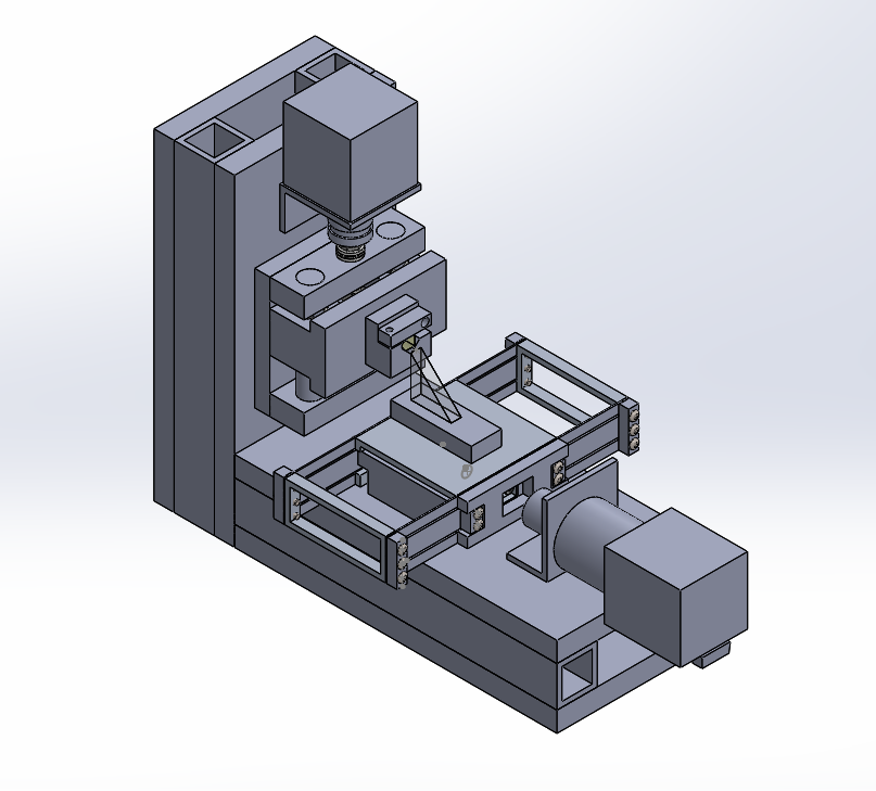
In this post I start with an overall summary of the machine, followed by a discussion of each module along with the calculations I did to support my design decisions. Any mistakes I made, are here for the world to see!
Machine summary
I designed the machine as three major modules – the X (feed) stage, Y (slice) stage, and Structure. Submodules include the X and Y built-up beams which comprise the structure, the knifeholder, and the specimen vise.
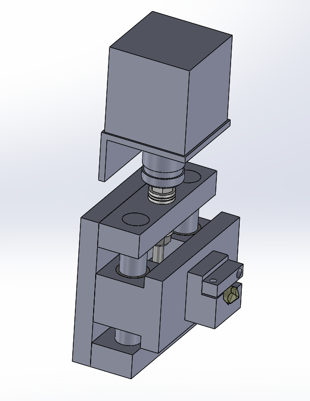
X stage
- Bearings
- Flexure
- Gearbox supports leadscrew thrust, radial (backlash?)
- Drive
- Stepper motor with 14:1 reduction couple to 1/4-80 leadscrew
- Decoupler
- Leadscrew drives X stage through decoupling nut (design in progress)
- Supporting worksheets
- x stage flexure design worksheet v1 – worksheet to design the main flexure bearing
- X decoupler flexure design worksheet v1 – worksheet to design the decoupler flexure
- X stepper motor and leadscrew reduction v1 – worksheet to calculate what resolutions I could get from a stepper motor
- Knifeholder
I’m working on a new concept for a knifeholder with high stiffness and large angle adjustment range based on line contact and planar kinematics (see video below…video worth a thousand words!). I need to figure out the details of preloading/stiffness/etc but the concept looks promising
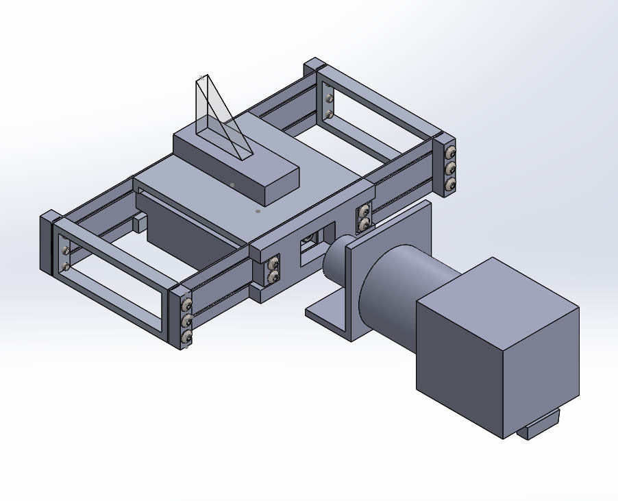
Y stage
- Bearings
- Two ball thrust bearings support the leadscrew’s thrust forces and one sleeve bearing supports it radially; other end unconstrained
- Drive
- Stepper motor with 10-32 leadscrew
- Decoupler
- Using the HeliCal coupling given to us
- Supporting calculations
- y axis leadscrew design v1 – various leadscrew-related calculations
- bushing linera stage stiffness – Used to calculate stiffness of a two-rod bushing stage and friction in the bushings
- ball slide stage stiffness – I used this to evaluate a stage concept that used balls
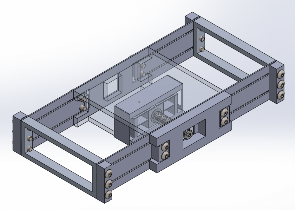
Structure
- Reinforcement – I would also like to have a gusset of some sort but I need to get back to the error budget and figure out how much stiffness I need from the structure
- Supporting worksheets:
Seek n Geek 8: Mitee Bite cam clamp
Mitee-Bite’s low profile cam clamps – these are used in machining fixtures to hold parts during cutting.

Source: http://www.miteebite.com/products/fixture-clamps/
Functional requirements
- Must be able to resist machining forces
- Must not loosen due to cutting vibration
- Must have a low profile
It looks like this design puts the bolt under severe shear loading. As you screw the bolt down, friction between the bottom of the bolt head and the brass clamp causes it to rotate into the part being clamped. The amount of clamping is controlled by the eccentricity of the bolt head so this is a displacement controlled process, and with large stiffnesses this translates to large forces. A 1/4-20 cam clamp is rated for 800 lbs of holding force; I’ve calculated that this puts the shear force at about 100 MPa, which is well within what a socket head cap screw can handle.
PUPS 8: Build and test the MCM
Summary
I’m still behind schedule but am making progress! I’m finishing up details on the MCM, and over the weekend will do design work on the rest of the machine and the parts I’ll need for characterization (cap probe holders, for example). I’ll be able to start machining next week.
Analysis worksheets for this week:
- Blade flexure out-of-plane stiffness correction factor worksheet
- Latest error budget
- Geared stepper motor and leadscrew resolution
- X stage flexure design worksheet
Error budget updating and sanity-checking
Last week I was deciding on whether I should go with flexural bearings, rolling contact, or a kinematic sliding contact stage for my most critical module (the knife positioner – has to position to an accuracy of 100nm or better). The lowest risk solution is a flexure stage, since I know for sure that these can achieve repeatabilities on that scale. I would have to work harder to make the other two types of bearings perform at that level (I would be higher up on the cost/performance curve).
With flexural bearings, I need to be careful that my stiffnesses are appropriate to my application (this is true for any bearings, but with flexures it’s easy to accidentally decrease a stiffness that you wanted to keep stiff!). I need to use the error budget as my guide – in PUPS 7 I noticed that I needed to update the compliance matrices for my two flexural bearing stages (and in general I had been sloppy with double-checking to make sure there were no errors). I created analytical models for blade flexures (I used Dr. Layton Hale’s thesis to get some of the more complicated analytical solutions, but it turns out using simple beam equations is almost good enough). Once I knew my target stiffnesses I could do the detailed flexure designing (what range? stresses? fatigue? that sort of thing).
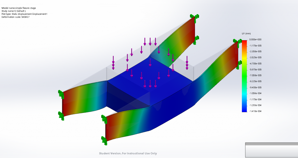
I went into the error budget and updated the compliance matrices for my flexures, and because of how important this is to my machine I decided I would validate my analytical flexure stiffness models with FEA. What I found was that my analytical model overpredicted the out-of-plane stiffness of a single blade flexure by a factor of two (I treated it as a fixed-guided beam), and this overprediction propagated into the rotational stiffnesses, so I needed to figure out why this is happening (the other stiffnesses were within a few percent).
I talked to Marty about this and he mentioned that for deep beams, one needs to apply a correction factor for internal shear. I looked in the literature to find solutions to deep beams (I didn’t want to solve the differential equations from scratch). I rearranged the formulae and found that you could write the internal shear correction factor as a dimensionless factor that relies on the depth-to-length ratio. I applied this correction in my error budget and the analytical model was within a few percent of the FEA (I tried it with various beam depths, and the corrected stiffness was consistently within at least 10%).
Design work
My MCM is the knife positioner module with a flexure bearing and I’ve been focusing on narrowing down what it will look like.
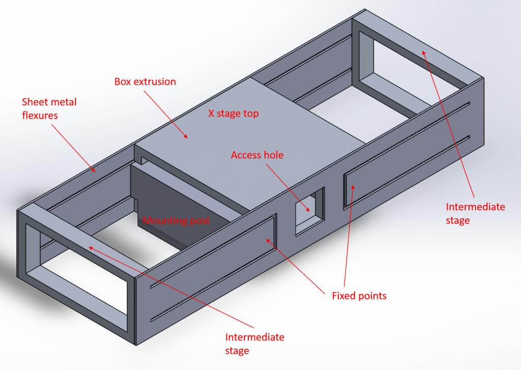
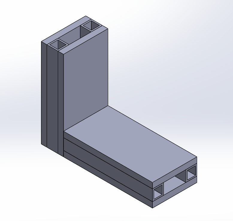
To get the range I needed, I could either have very long flexures or I could fold them over – I chose to have the more compact, but more complex, design. The flexures themselves are cut into sheet metal in two pieces; if I minimize the possibility of misaligning flexures during bolting-together, I’ll minimize parasitic error motions caused by those misalignments. These will also cut very quickly on the waterjet and so will be very cheap to make. I’m working on finalizing the details and streamlining the design as much as I can.
Differential leadscrew concept
I figured I could get high range and high resolution by using a differential leadscrew arrangement, but as I worked on this I realized that the complexity was increasing
The key issues I faced with this design were:
- The motor has to move with the screw, which means I need another bearing!
- I calculated that the screw has to move approximately 2 inches to get a full 1/4″ of motion at the output
I wondered if I could get away with a simpler solution, with a geared-down motor directly driving a fine-pitch screw.
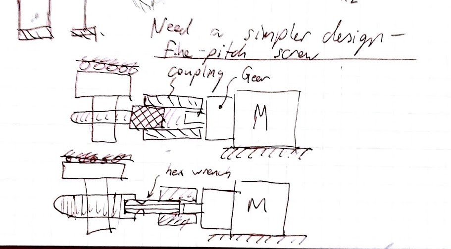
This is a much simpler, more compact design, but will it work effectively? The motor and gearbox are rated for 50 N of load, so it will handle the axial load comfortably (I push/pull with a maximum of 15N). What about misalignments? I won’t be able to get this thing perfectly aligned, I may have to build in some decoupling flexures into the carriage nut (or use a non-rigid coupling). I will figure out which misalignments are most likely to be problematic and decouple those. The nuclear option: I have a design for a decoupling stage that can move in every degree of freedom except the wind-up direction. I could attach the leadscrew nut to this stage, and then couple this stage to the X stage via a wire flexure to transmit only the axial component of motion.
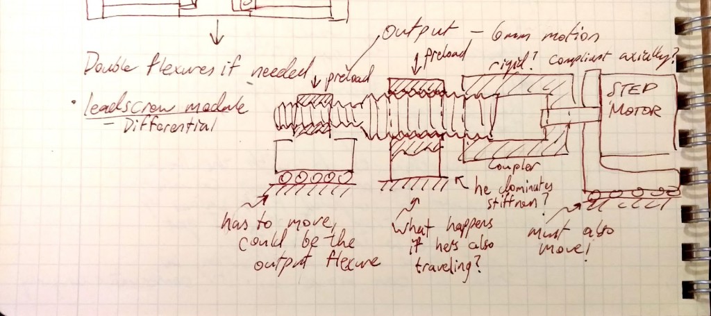
This is getting complicated! I’m not comfortable with this concept because I would have to design it to move as far as my X-stage – I would have to double-design my X stage! First I need to asses which error motions are important , and roughly what I expect their magnitudes to be given my assembly and machining tolerances (which errors would cause the system to bind up or generate huge loads?). Could I use an off-the-shelf coupling? Below is a screenshot from my notebook where I estimated what these errors would be.
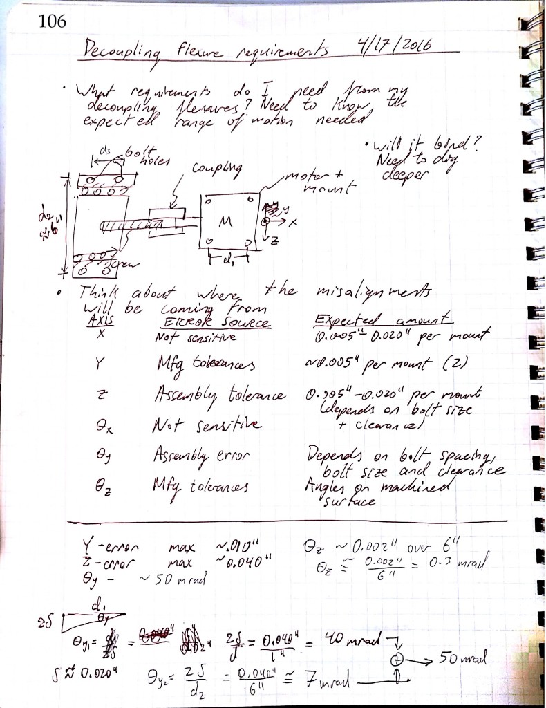
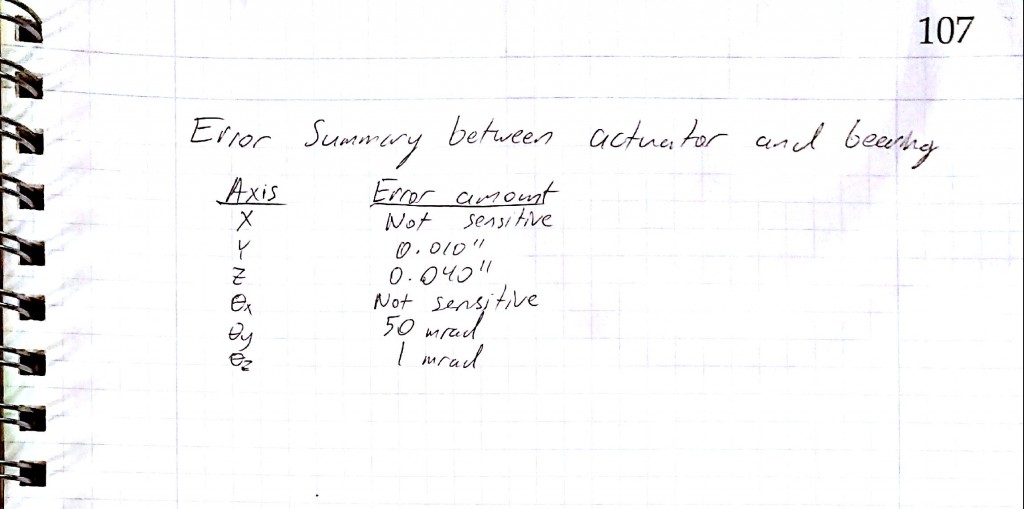
A quick survey of couplings on Mc-Master shows that the helical-type couplings only tolerate parallel misalignments of a few thousandths and angular misalignments of a few degrees. Most of my parallel errors are creeping in due to using bolts as clamping+alignment. If I use dowels to locate parts (so that my positioning uncertainty is reduced from around 0.020″ to about 0.002″), I can reduce the parallel errors by about an order of magnitude. I can now use a helical coupling.
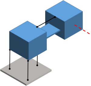
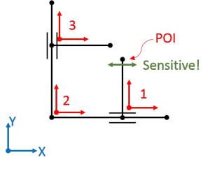
Alternatively, here’s a modified error motion absorbing concept with 4 degrees of freedom (this is schematically the same as the “dancing man” flexure from 2.72, which is used to decouple leadscrew error motions from the carriage while remaining stiff in the torsional and axial directions). I don’t have lots of room inside my carriage so I’d prefer to build this into the motor mount.
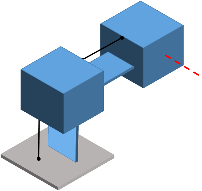
An implementation of the above schematic is shown below. It’s more complex than the helical coupling, but I’ll keep this in my quiver in case the helical coupling doesn’t work out.
For my actuator I’ve chosen a stepper motor with a gear reduction of 14:1 – this combined with a fine-pitch screw (1/4-80) will theoretically give me a resolution of ~ 60 nm. Steppers are inexpensive and simple to interface with, and driver chips are cheap and ubiquitous nowadays thanks to the DIY 3D printer crowd. Torque to actuate shouldn’t be a problem – I calculated a torque-to-move of about 0.01 N-m (from the Geared Stepper motor worksheet) under a heavy load of 50 N; my motor will be able to exert around 1 N-m. The gearbox is rated for a 50N axial load and a 100N radial load, and my current flexure design will take at most 20N to move.
For now – I need to finish detailing the MCM and finish working on the rest of the machine. My next step is to detail the MCM (bolts, etc), cut out the parts, and then test it
PUPS 7: Machine Design Concept Detail Exploration
Synopsis
I’m trying to position a knife to 100 nm accuracy for an epoxy slicer. My challenge – can I do it for cheap by using the fundamentals?
Where I’m currently at – I found an error in my error budget spreadsheet (ironically enough) and I need to stop, fix it, and double check for other errors before moving on (otherwise I could be basing an entire design on some bad math!). Details – I forgot to update the compliance matrix on some of my coordinate systems, and the F=kx errors the default values gave me were better than what I should have so this slipped past me.
A note on sensors, since the PUPS doesn’t mention them – I don’t think I can run my machine open-loop; I’ll need feedback to close the loop, and also to characterize the machine.
- Interferometer, simple Michelson type – if I set this up right I can get six-DOF measurement to characterize my stage. That makes it incredibly appealing! But aligning the beamlines will be difficult. I’ll need to spend some money on beamsplitters and a good quality laser source (I don’t think the cheapie laser diodes will be stable enough to be useful, but it’s worth checking out) – ThorLabs has a good selection. I think I will pursue this for 2.77
- Capacitance – I can buy capacitance-to-digital ICs for cheap. Would have to do some calculations to figure out if this would give me reasonable resolution and accuracy, and I would have to design/build a bunch of them to get multi-dof measurement. I prefer to pursue the interferometer.
PUPS questions
1. Design (and/or select) the bearings, bearing rails, and actuator to handle the loads and provide the stiffness and accuracy as indicated from your previous error budgeting work
I’m taking a modular approach – I’d like to spec the actuator separately from the bearing system, and connect them kinematically with wire flexures for example, since in my case there’s a decent chance my actuator may not be able to achieve the desired resolution (due to stiction for example).
Actuator options
- Leadscrew + stepper – This would be a very inexpensive solution (less than $100) if I can get this to work. I’ve calculated that using a NEMA-17 motor with a 10:1 reduction gearbox and a 1/4-80 screw, I can get a step resolution of about 80 nm, which is right on the money! But will I actually be able to take a step that small? I’m working on estimating how much friction will be in the system.
- Differential leadscrew + stepper – Similar to above, but get rid of the reduction gearbox and use a differential leadscrew to boost resolution. Is this any better?
- Thermal inchworm – similar to a piezo-based inchworm, but using thermal expansion elements instead of piezo actuators. Much cheaper, but it would also be much slower (average speed of around 0.01 mm/s) and would require a significant amount of engineering effort. I decided not to pursue it.
- Leadscrew+stepper (coarse) in series with piezo (fine) – coarse/fine arrangement with a leadscrew to get me coarse motion, and a piezo to get me the last few microns.
- Piezo inchworm – off-the-shelf solutions are available but expensive. Building my own would require three piezo elements. The piezos themselves are expensive (over $100 each), I could get away with building my own simple electronics since the inchworm only requires on/off (a more sophisticated version of this puts the expansion piezo under fine control when approaching the final position, so the stepper doesn’t overshoot the desired position).
- Friction drive + stepper – This would behave somewhat like a rack and pinion, I would need to pay careful attention to the contact stresses and make sure the stepper has enough resolution.
- Voice coils – cheap to make and easy to control, but I don’t get much force or stiffness out of them and they dissipate lots of heat.
Bearings
I’ve so far considered sliding contact, rolling element, and flexural bearings. I’m trying to achieve better than 100 nm positioning resolution – assuming I’m not limited by the actuator, the flexure can easily achieve that, but what about rolling and sliding contact bearings?
Sliding contact – I have read papers (such as the Nanosurf 2 paper by Lindsey, Smith, and Robbie from 1988) detailing the design of sliding contact based nanopositioners. I could use off-the-shelf components that already have good surface finishes (like glass lenses, glass plates, and ground steel rods) to make a kinematic slideway.
I used the 2.75 Hertzian contact worksheet to check how feasible, load- and stiffness-wise, a kinematic slide design would be. For a total load of 100N, it looks like 1/2″ diameter balls would suffice.
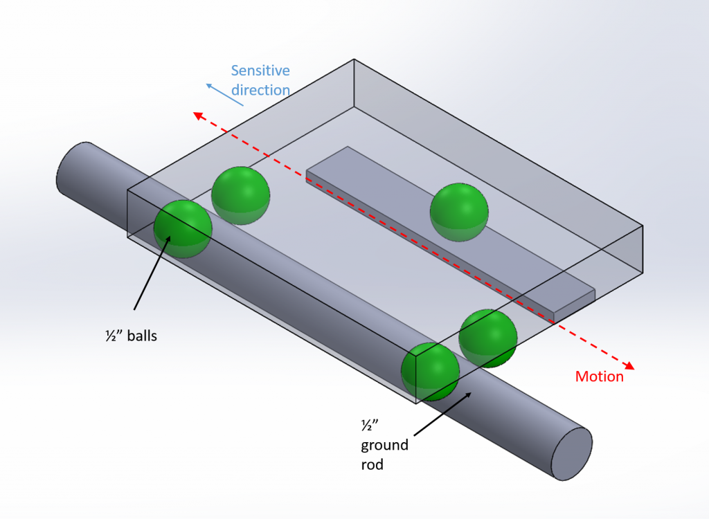
A stage like this would be cheap and easy to build. How much stiction would it have?
Rolling contact – An off-the-shelf precision stage would be expensive, but I think I can make my own by combining purchased steel balls and precision ground rod.
Flexure bearings – my instrument currently has two flexural bearings, but are they the best tool for the job?
So here’s an idea – my instrument needs two stages, why not design one stage as sliding contact and one as rolling contact? (unless one of these is grossly inappropriate for the application…). I think I can build two stages with the same size parts, so I most likely won’t do this.
2. Design the support structures for the bearings and actuator and its attachment to the rest of the machine to meet the stiffness and accuracy required
In progress: fixing the error budget to get an appropriate stiffness target for each element
3. Design the carriages and attachment to the bearings (or rails) and to which other elements will be attached, to meet the stiffness and accuracy required
In progress: fixing the error budget to get an appropriate stiffness target for each element
4. Update the error budget and FRDPARRC table and if needed iterate on the design
Fixing the error budget
5. Solid model with just enough detail the linear motion axis parts and assembly to enable you to make part toleranced part drawings to build the most critical axis of your machine
To-do
Seek and Geek 7: Inchworm motor
While looking for actuators that could get both nm-level precision and mm-range length of travel I stumbled across inchworm actuators.
An animation of the inchworm concept can be found at:
https://en.wikipedia.org/wiki/Inchworm_motor
What kinds of things would I be concerned about if I were designing an inchworm motor?
Functional requirements
- Step size
- Stiffness
- Holding force
- Not destroying the piezo crystals
- Frequency of operation
Design parameters
- Step size
- Depends on the expansion of the central piezo element
- Depends on how the central piezo element is controlled (are we doing on/off control, or trying to carefully control its expansion?)
- Stiffness
- Shear stiffness of piezos
- Any other elements in series with the piezos (what are they mounted to, for example?)
- Holding force
- Based on friction
- Not destroying the piezos
- Kinematic mounting, look out for edge loading
- Flexures
- Spherical tips
- Not overloading the piezos, pay attention to mfger maximum compressive loads
- Kinematic mounting, look out for edge loading
- Frequency of operation
- Higher = more power dissipated?
- Consult mfger literature
Also of concern:
- Geometric goodness of the rod being gripped – if it changes diameter for example, this will impact the clamping strength
- Surface finish of the rod being gripped – needs to be consistent for consistent stepping and clamping
- Rod bearings – what’s guiding the rod? Will it exert a moment on the actuator?
Seek n’ Geek 6: Sliding closet door
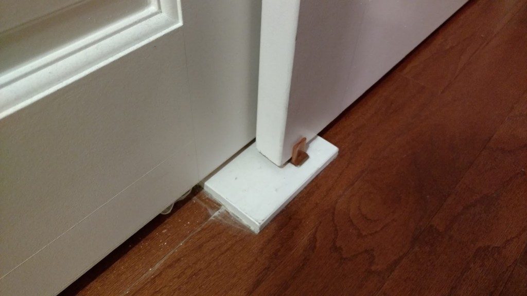
For this week’s Seek and Geek, I’m looking at a sliding closet door, which is an interesting instance of a linear slide.

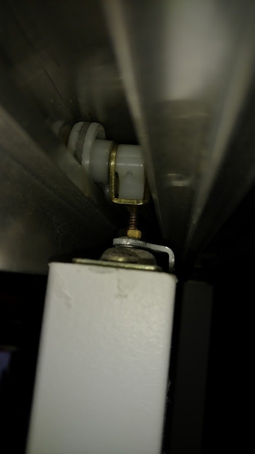
First thing I noticed is that the door is guided from the top only – the bottom only has a plastic retaining clip to prevent the door from swinging too far out.
Taking a sneak peek into the rail above the door reveals that there are two sets of rollers holding up the door.
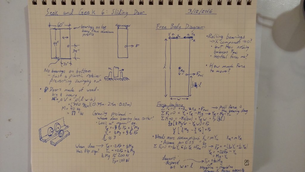
My analysis this week considers the pulling force on the door – how hard would one have to pull to cause the door to lift off one of the bearings and possibly jam? With my estimate for the weight of the door, it’s about 25 lbf [100 N], but because the door uses rolling element bearings it takes much less force than that (about 2 lbf) to get the door moving, so we never reach that level of force.
PUPS 6: Machine Design Concept Detailed error budgeting
For this week’s peer review session, we met up and helped each other understand the big error budget spreadsheet. My major effort this week was to modify the spreadsheet to allow me to include a first-order model of a flexural bearing
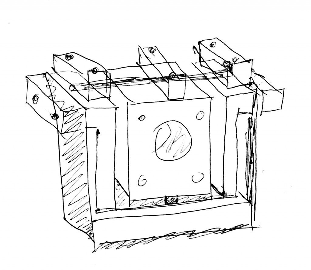
A stick figure model of the machine concept I’m looking at today is shown below.
Create first order error budgets for your favorite design(s)
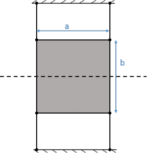
The most challenging part of this machine will be controlling the accuracy in the X direction to 100 nm, on a budget! At this point I’m reasoning that any off-the-shelf rolling-contact stage that can achieve this kind of accuracy and precision will most likely be outside of my budget (if I have to ask for a quote, I probably can’t afford it!). Therefore for now I’ll assume I’m using a symmetric parallelogram flexural bearing for first-order error budgeting – stiffnesses I can estimate with beam bending and axial stiffness, and geometric error motions I can estimate from similar stages (for example, R.V. Jones’ flexure stages as described in his papers from the 1950s – he characterized the error motions of similar flexure-guided stages over a range of about 6 mm, before and after ‘tuning’ the leaf springs for maximum perfromance).
Alternatively, before I lock myself into using flexures, I could consider building a kinematic stage out of precision ground cylinders, balls, and flat ground plates – but for this week I’ll focus on the error budget spreadsheet.
Model preload method envisioned for the bearings and its effect on stiffness, bearing life, accuracy…especially given manufacturing limitations
Fortunately I don’t have to worry about preloading my flexure stage just yet – however this will get tricky once I have to hook it up to an actuator. I will have to be careful with my fatigue calculations, and my manufacturing limitations will induce motion error.
I could try to get around manufacturing errors by elastic averaging – instead of having 4 blade flexures, I could add more blades (while keeping the same constraint) and perhaps average out the manufacturing variations – but I would have to look closely at how I plan to make them first to see if this would actually be effective. For now, I’m leaning towards using the minimum number of blades required so that if I have to tune the blades, it’ll be easier to find which blades need to be tuned.
Update error budgets
For the error budget, I renamed Axis 1 to be my X bearing. I added a column under ‘bearings, servo, structure’ and defined a parametric stiffness model for a blade flexure.
I need to check in detail that the results make sense (that the blade stiffness models are reasonably accurate – verify via FEA, and that the error budget spreadsheet output makes sense) – then I can duplicate the X axis bearing for the Y axis, and add structural information for the intermediate axis.
error_budget_spreadsheet_2016.03.09_aeram
Assess Risks and Countermeasures and use to evolve designs and trim options to help converge on top two designs (or maybe even 1)
The two designs (the second one is shown in PUPS 5) I’m considering are similar enough that I’m not sure first-order modeling will capture the better design – once I start to get into actuator and sensor placement, a clear winner may emerge. Right now, my biggest concern is that a flexural stage will be too compliant to achieve my desired precision/stiffness, especially if I have two in my structural loop! I need to take some time and see if I can make the stage stiff enough while still having the required range of motion and being actuate-able.
Update to error budget
Here’s an updated version of the spreadsheet – it turns out I had put in some negative values for some of the random bearing errors and that played havoc with the angular error logic (I was getting an epsilon_x value of about a radian!). With the bug corrected I’m getting much more reasonable error values now, see below (and I left the old one up top for comparison’s sake)
Seek n’ Geek 5: Wooden napkin holder
For this week’s Seek n’ Geek, I’m looking at a wooden napkin holder that relies on friction to hold napkins in place. In particular, I’m wondering how it can maintain it’s holding ability despite not having any sort of adjusting mechanism to tighten up the pivot. It also seems like a difficult manufacturing challenge to make these repeatably enough so that each napkin holder has just the right amount of friction – too loose and they flop over, too tight and they’re frustrating to use or they break.
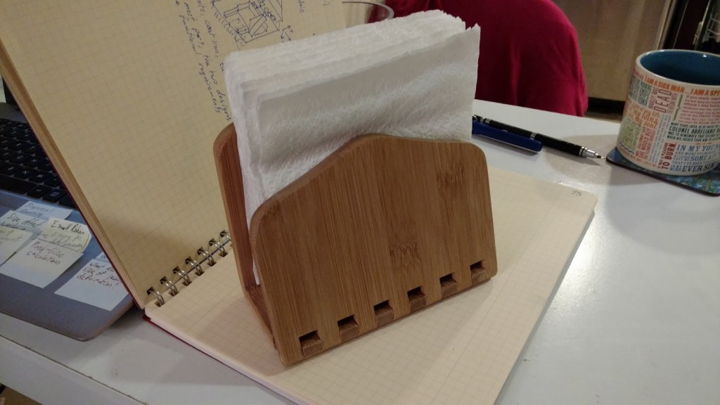
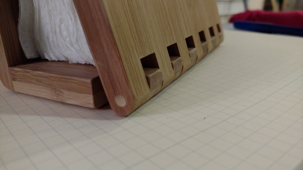
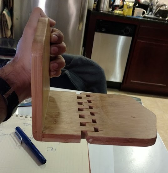
The first thing I notice is that there’s no slop in the joint, I can’t wiggle it around at all. If I hold up the joints to the light, I can see gaps between some of the fingers – it looks like not all of the finger pairs have pins between them; the only fingers that I can see for sure that have pins are the leftmost and rightmost pair of fingers. The mechanism appears to loosen up as it approaches 45 degrees from the plane of the table, and then it tightens up again. What’s going on here?
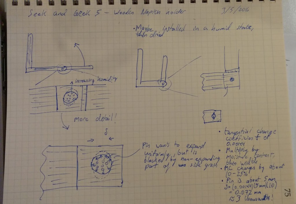
I can at least say that the direction-dependent properties of the wood don’t affect much here – since the grain of the wood is aligned, any expansion due to humidity change would affect both sets of fingers equally and there would be no net contraction or expansion. On the other hand, the pivot dowels are drilled and installed into side grain – the hole won’t expand uniformly
When I close the napkin holder, I can see that some of the fingers have gaps on both sides – there’s no engagement, and those fingers don’t contribute to the friction.
2 fingers have gaps on both sides, and 2 fingers have gaps on one side, so out of 12 possible contact surfaces, half are not in contact.
It seems that since there’s so many fingers it would be difficult to keep a tight enough control on the manufacturing process to keep the holders from being too tight or too lose – is there a more deterministic method that is being used to preload the pivot and provide friction?
Here’s one idea: the holders are manufactured and assembled in a very dry state; because the pivots are drilled into side grain, the side grain won’t expand uniformly and the pivot will preload itself against the hole upon reintroduction to a moist atmosphere
To test this hypothesis, I did an experiment – I held the napkin holder over a boiling kettle for a few minutes, and if my hypothesis was right, I should see the stiffness of the pivot increase. Sure enough, the swinging part was now more difficult to turn – it would no longer fall under its own weight, even when held horizontally!
I did some calculations to verify that this is feasible – I looked up the dimensional change coefficient of bamboo, and assumed that the moisture content increased by about 10% from when it was made and when it was being used. This results in the pivot dowel being pinched by about 75 microns, or 0.003 inches! That seems about right.
I did a brief search online but couldn’t find any information about whether or not this is how these are designed to be made! I’m very curious now, so if anyone knows for certain I’d be happy to hear about it!